"Patent Pages"
by Ray Klingensmith
Reprinted from "INSULATORS - Crown Jewels of the Wire", April 1981, page 3
J. F. BUZBY PATENT
On May 6, 1890 a patent for an insulator for use
with wires on telegraph or telephone poles was issued to Joseph F. Buzby of
Royer's Ford, Pennsylvania. The insulator shown in the patent drawing had a top
portion with a perpendicular slot in which the wire rested and a "open
communicating slot arranged at an oblique angle". The purpose of the
arrangement was to allow the wire to be inserted into the angled slot, and upon
gaining full entrance it would settle into the perpendicular slot. This would
prohibit the line wire from escaping. This is a very interesting design, and to
have a better idea of the construction, I suggest viewing the photos and
drawings. The patent application also included a far fetched method of securing
the insulator to the pole, rather than using a regular threaded pin. However,
since the insulator has been found with a threaded interior only, I felt I would
save a lot of confusion and not include that part of the patent concerning the
fastener.
Several years ago two Busby patent insulators were found in the
Binghamton, New York area. About three years ago another one was found in
Binghamton. If I'm not mistaken, the third one was found the site of an urban
renewal project. Apparently these were used often a telephone or telegraph line
through Binghamton. At the present time these three are the only ones I know of.
Two are of a light greenish aqua glass, and the other is dark aqua. The threaded
pinhole is very near the base, with a "swirl start" at the base of the
thread. The glass between the pinhole and outside skirt area is nearly one inch
thick.
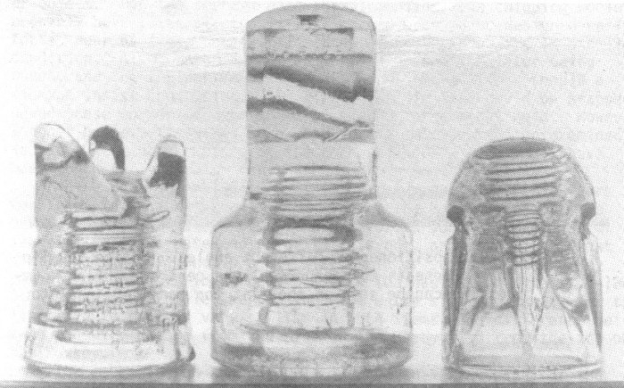
These insulators are rather tall, with a height of 5-1/4 inches as can be
seen in figure one, in a comparison with two other insulators.

Large Image (94 Kb)
Fig. 1 - The size
of the Buzby can be seen here, in comparing it with
the large style Harloe and
Chicago pony.
Large Image (130 Kb)
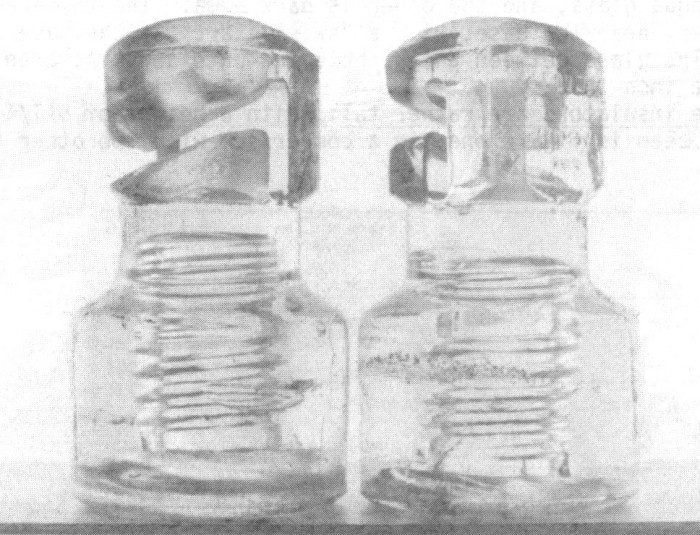
Fig. 2 - A rare family reunion, two of the three known
Buzbys.

Large Image (110 Kb)
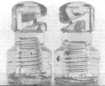
Fig. 3 - Buzbys positioned at different angles.
Notice the lip formed
beneath the corners
at the central portion. Embossing can
be seen on the flat
top panel on insulator at right.
Large Image (30 Kb)
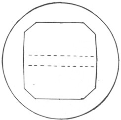
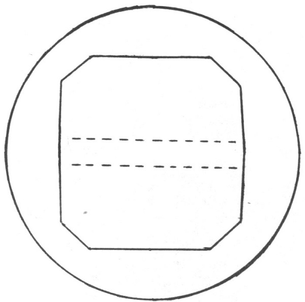
Fig. 4 - Top view showing beveled
corners of upper portion,
and dotted lines at the location of the interior line
wire cavity.

Large Image (34 Kb)
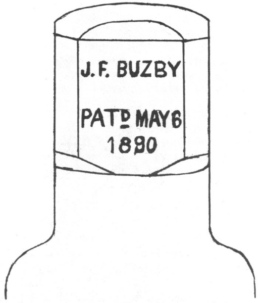
Fig. 5 - Partial drawing showing location
of embossing on the flat
panel.
This style is a rather complicated design, and I'm sure the mold maker
had some fun trying to figure out how to make the mold for these. It seems the
most complicated part of forming the insulator would be the angled slot for the
entrance of the wire, and the inner area where the line wire rested. Another
interesting feature of the insulator is the beveled corners at the upper portion
of insulator, as can be seen in the top view drawing. I would assume it was
designed that way to prevent breakage when coming in contact with another
object. Had the corners been sharp, considerable chipping would probably have
taken place. It must have proven to be designed well, for as near as I can
recall, all three of those known are in excellent condition. Also, with the
center portion of the insulator being round, and the top part nearly square, it
forms a "lip", should a lineman insist upon using a tie wire. The tie
wire could be wrapped under these corners and over the line wire for a tight
hold. However, I don't believe tie wires were used on the two Buzbys I've
examined, as there were no abrasions on the corners where a wire would have made
contact.
There were several different insulator patents over the years for types
that didn't require tie wires. The Buzby is one of the earlier ones, the patent
being applied for in 1889. There were a few similar types patented prior to this
one, and several somewhat similar after it. One in particular in later years is
the Purkey patent which exists in porcelain. Jack Tod has assigned to it U-186
in his Universal Style Chart. The wire entry slot and cavity for the line wire
to rest is very similar in both items, the difference being that the wire enters
from the side on the Buzby, and from the top on the Purkey.
The embossing on the
Buzby is located on a flat panel of the upper portion and is shown in figure
five. It's rather difficult to call this side the front! On an insulator shaped
like these critters, it's hard to decide what is the front and what is the
back?!
Large Image (118 Kb)
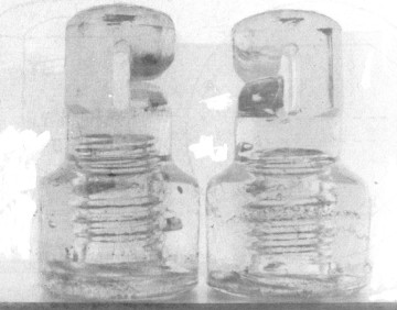
Fig. 6 - The different end positions showing the interior line
wire slot.
Large Image (139 Kb)
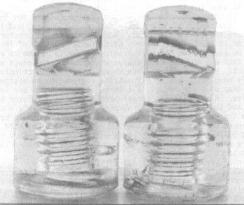
Fig. 7 - Insulator at left shows the angled slot for the entrance
of
line wire. One at right shows the opposite side,
with flat panel.
The
manufacturer of these is unknown. Wendall Hunter loaned me some of his material
awhile back, and in it was mentioned a glass company in Royer's Ford,
Pennsylvania, the home of Joseph Buzby. I'm not certain what type of glass was
produced there. These insulators could have been made in a nearby Philadelphia
or New Jersey glasshouse, or in one from some distance. There is very little to
go on at present, and I'm not about to make any guesses.
I'd like to say thanks
to both Glenn Drummond and Joe Maurath for the patent copy of this and several
other insulators, to Dieline Coleman for geographical information, and to Mike
Johnson (Ohio) for allowing me to photograph the three insulators from his
collection which are used in this article. Mike has been very helpful in the
past in allowing me to photograph many of the insulators in his collection.
At
this time I'd also like to inform all you folks that I may in the near future
get behind in my replies to letters. If you write to me and do not hear from me
right away, don't lose faith! As soon as the circumstances permit, I will get
back to you.
| 